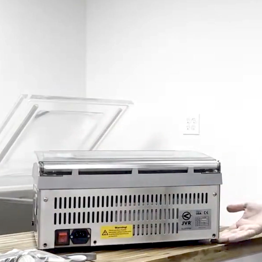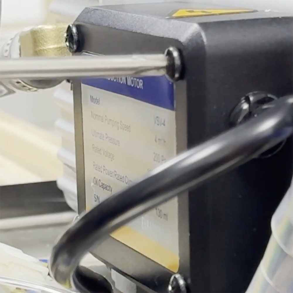

How to Replace the Valve Assembly (100-38) JVR Vac100 Thumbnail

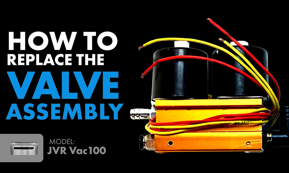
How To Replace The Valve Assembly (100-38): JVR Vac100 Chamber Vacuum Sealer


“The vacuum valve is a major component in the vacuum system that allows the oil pump to work effectively

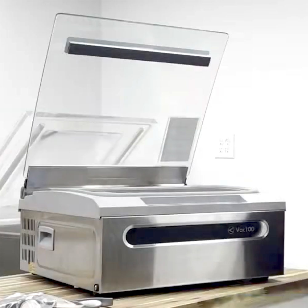
Each JVR Vac100 chamber sealer component is essential in bringing about the effective vacuum system that creates seamless vacuum sealing. Our team here at JVR Industries has pride in carrying more than 50 years of experience, and we are happy to provide the resources to keep your unit up and running! Today, we will be going over how to replace the valve assembly in your Vac100.

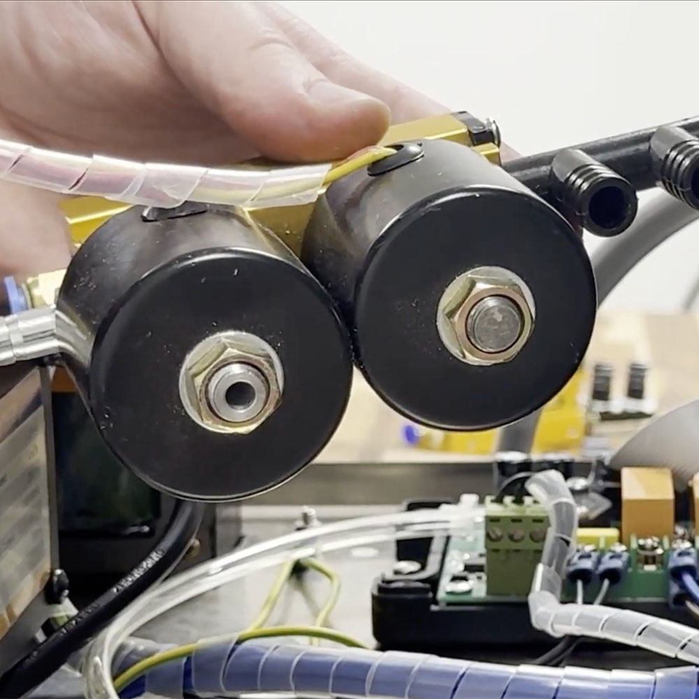
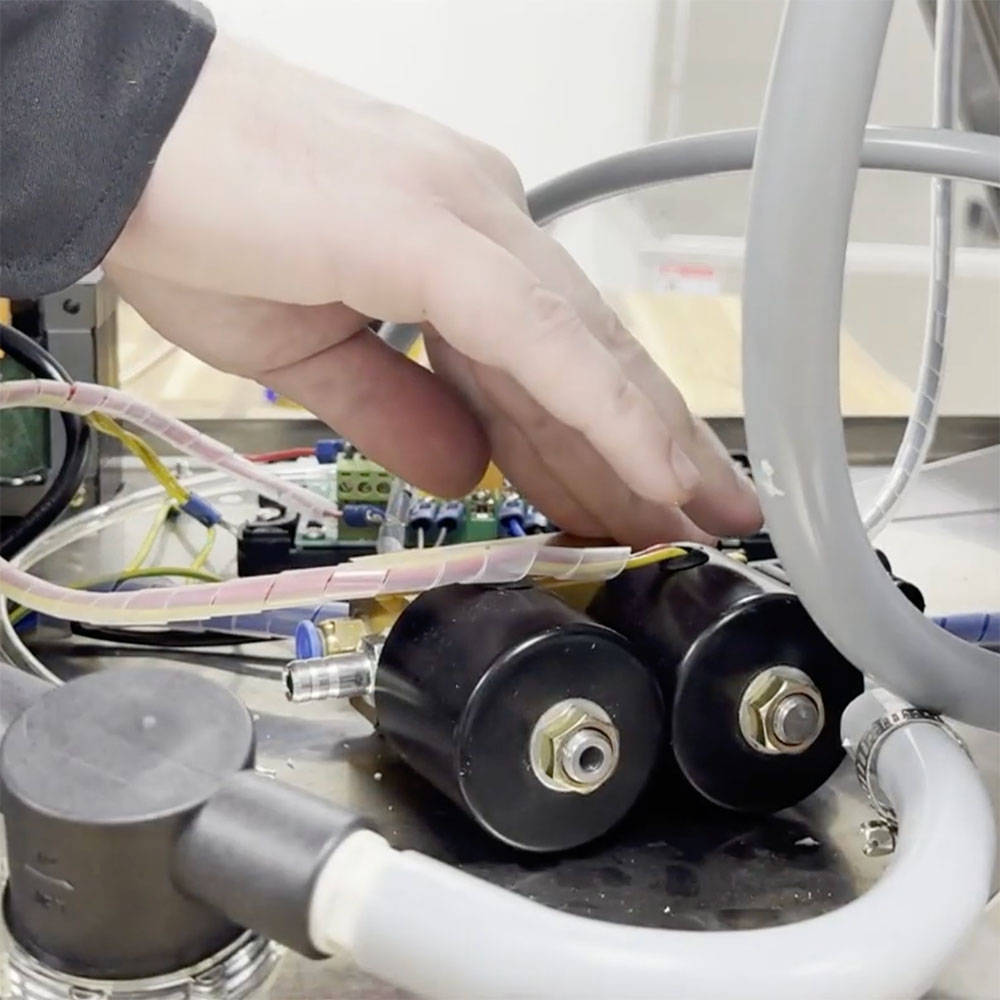
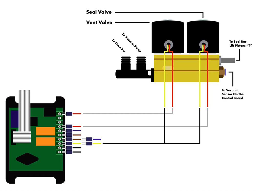
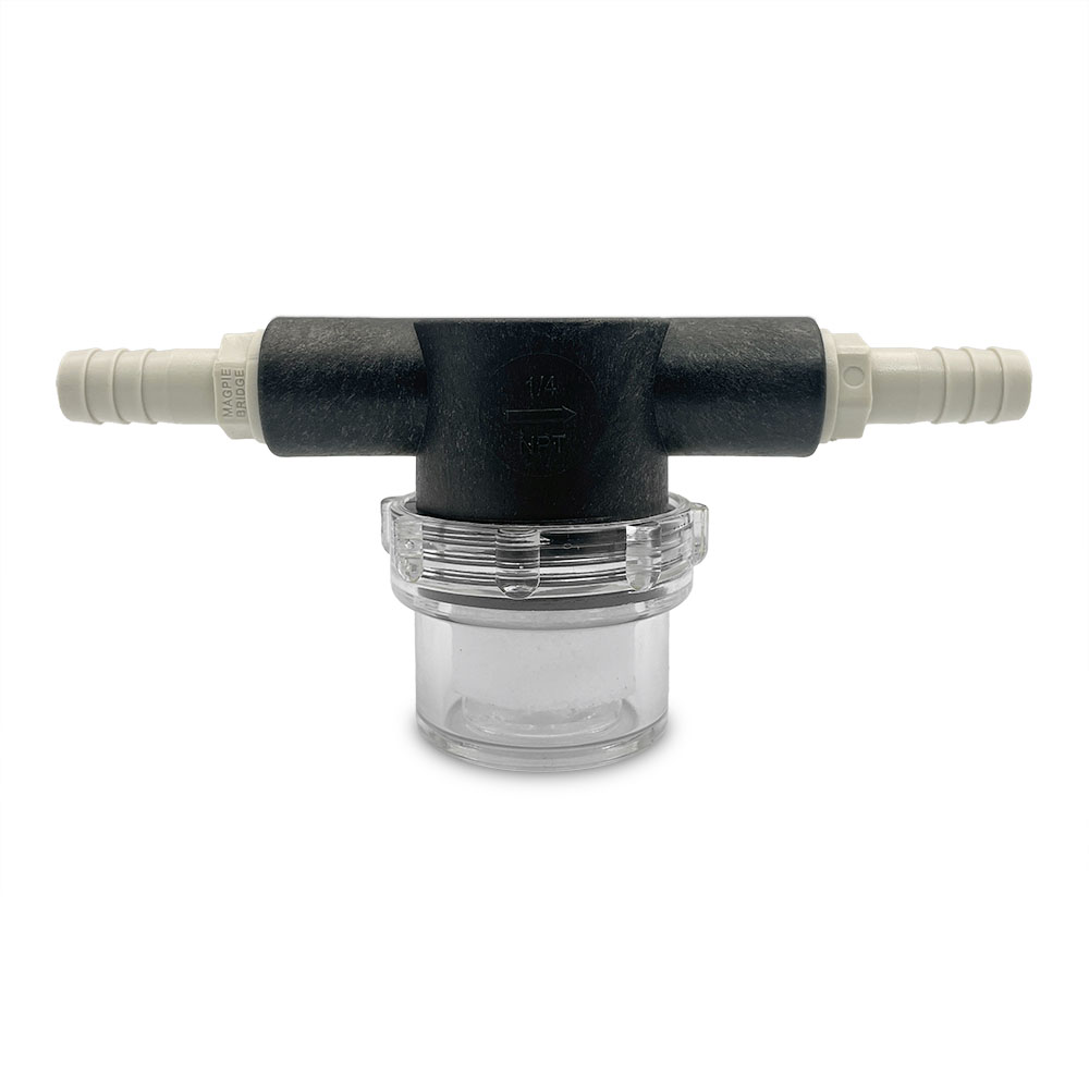
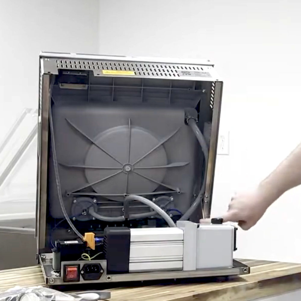
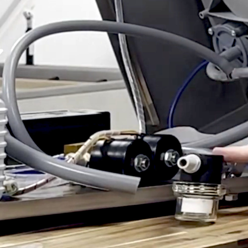
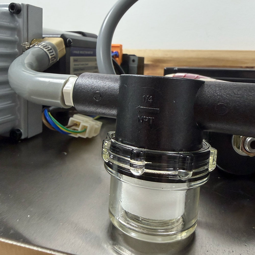
The valve assembly controls the path of airflow pulled from the chamber by the oil pump. The components include the seal valve, vent valve, power that goes to the seal bar pistons to create that perfect seal, and connections that lead to the vacuum sensor on the control board.

The vacuum valve is a major component in the vacuum system that allows the oil pump to work effectively, so you can do things like sous-vide meat with your favorite liquid marinade with outstanding effectiveness.

The valve assembly has a few different implications that indicate it needs to be replaced. The signs are not so straightforward as others. Therefore, we recommend calling our office to talk to a service technician to confirm the diagnosis before purchasing this part. It may just end up being a part of the whole assembly that needs to be replaced. We wouldn’t want the replacement process to be more expensive than it has to be for you.

Estimated to be about a 5-10 minute process.

4×4 Blocks Recommended

3mm Allen Key

#2 Phillips Screwdriver

Flathead Screwdriver

Right Angle Ratchet #2 Screwdriver

Valve Assembly (100-38)

Remove all items, including vacuum bags and filler plates, from the chamber before hinging the body forward.

Set unit on a stable surface with plenty of room.

Power off your unit and disconnect from the power supply.

Prep

1. Turn your unit so the back panel faces towards you.

2. Prop up the two closest feet on 4×4 blocks.

3. Remove the bottom 3 Allen screws found at the base of the back panel using the 3mm Allen key.

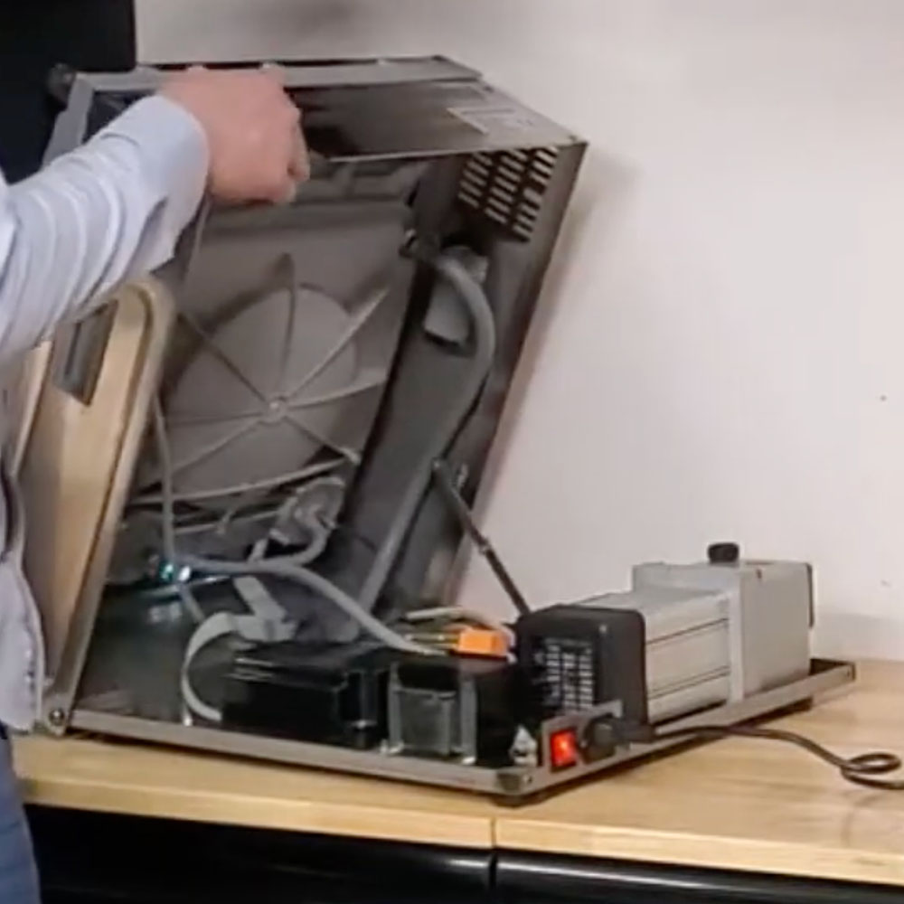
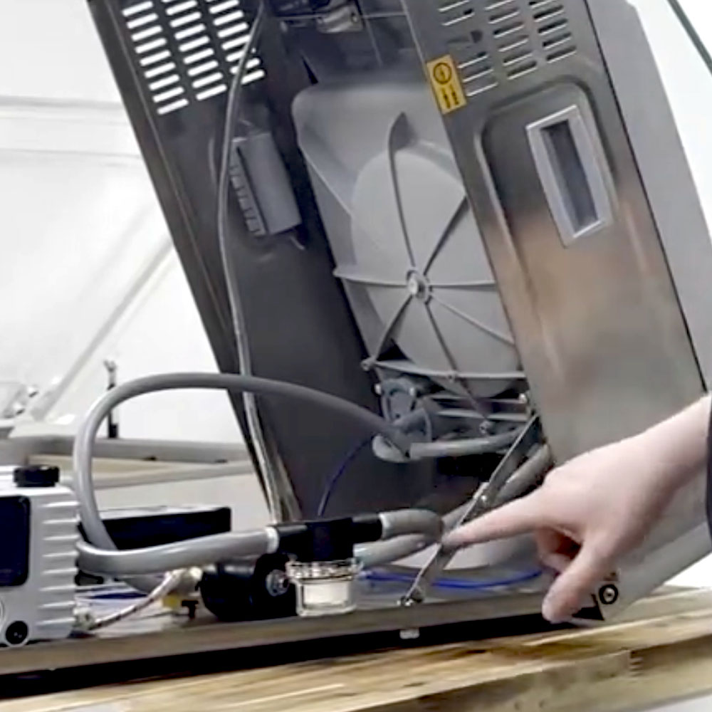
4. Hinge the external body forward and press the hinging mechanism to lock into place.

Disassembling

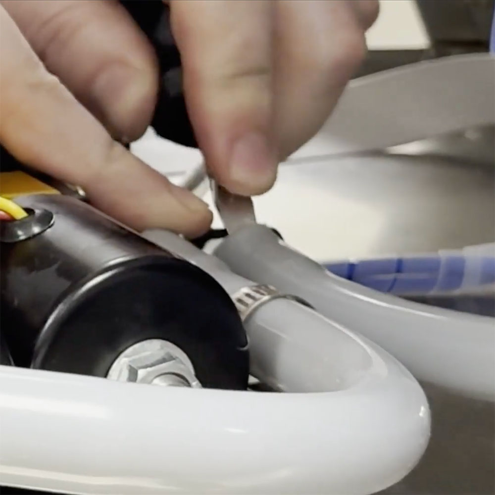
5. Remove the hose clamps with the flathead screwdriver.

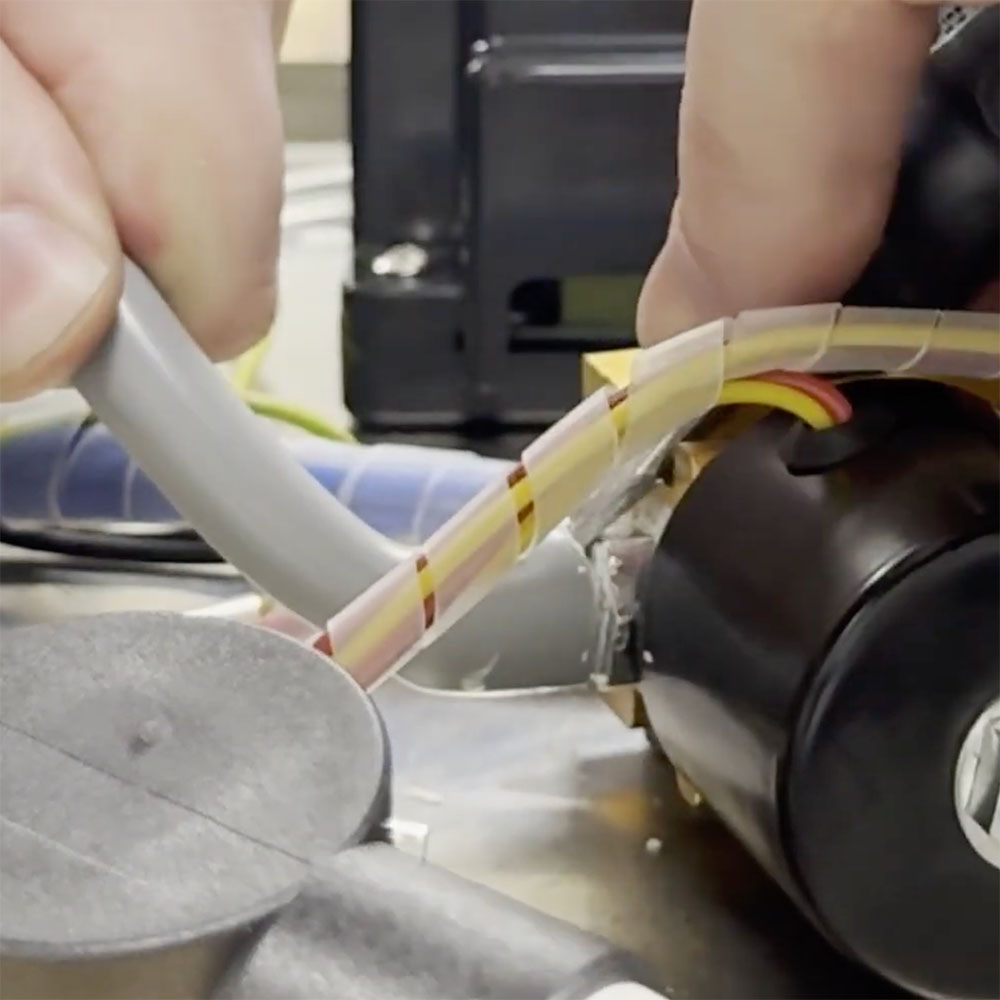
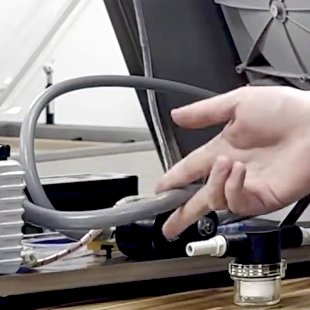
6. Remove the hose with the larger diameter. Work the flathead screwdriver around the mouth of the hose at a 45-degree angle.

NOTE: If you are concerned about tearing the hoses or are experiencing dry rot, you can always use a razor or strap cutters to cut the end off. Or purchase a new one (100-80, 100-81).

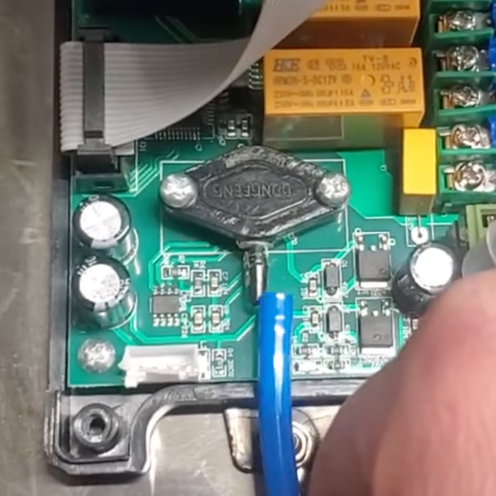
7. Remove the hose to the vacuum sensor via the blue push back.

8. Remove the smaller diameter hose (5.5mm).

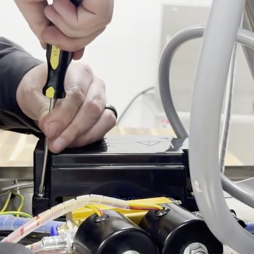
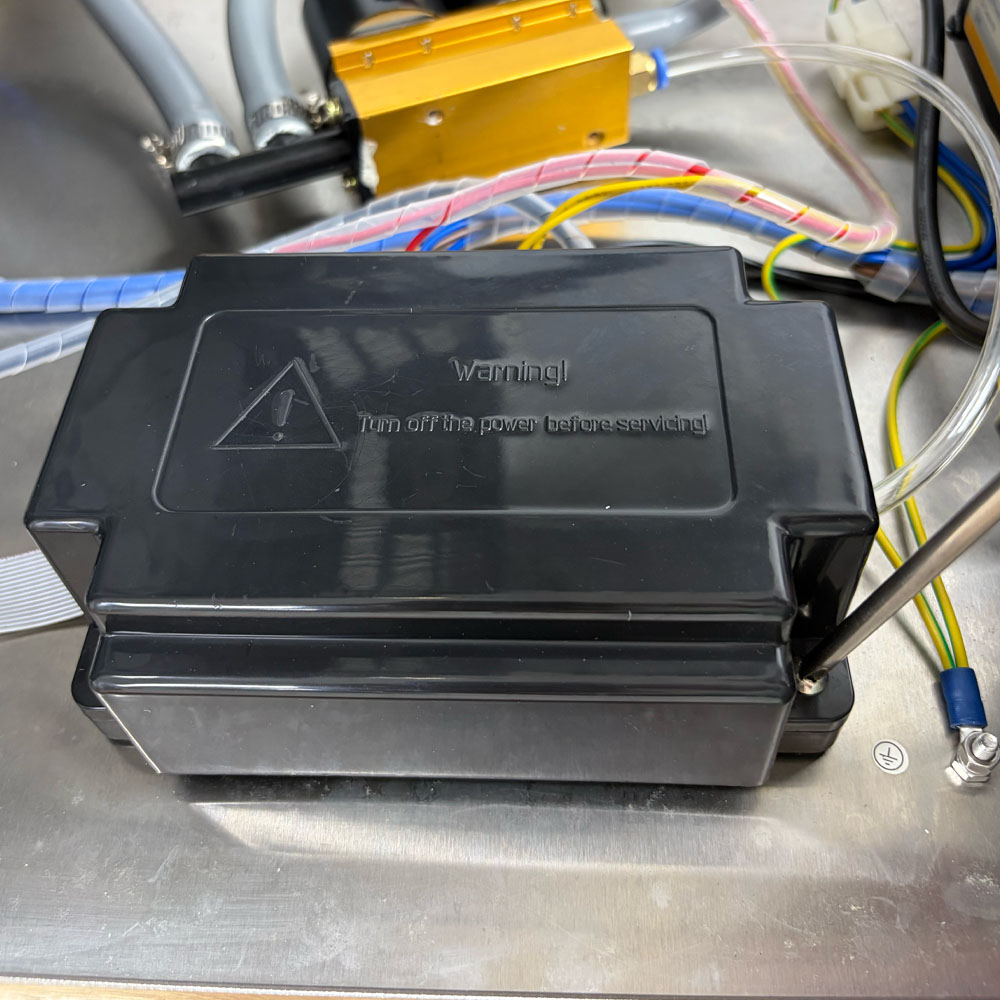
9. Remove the black box covering the control board using the #2 Phillips screwdriver.

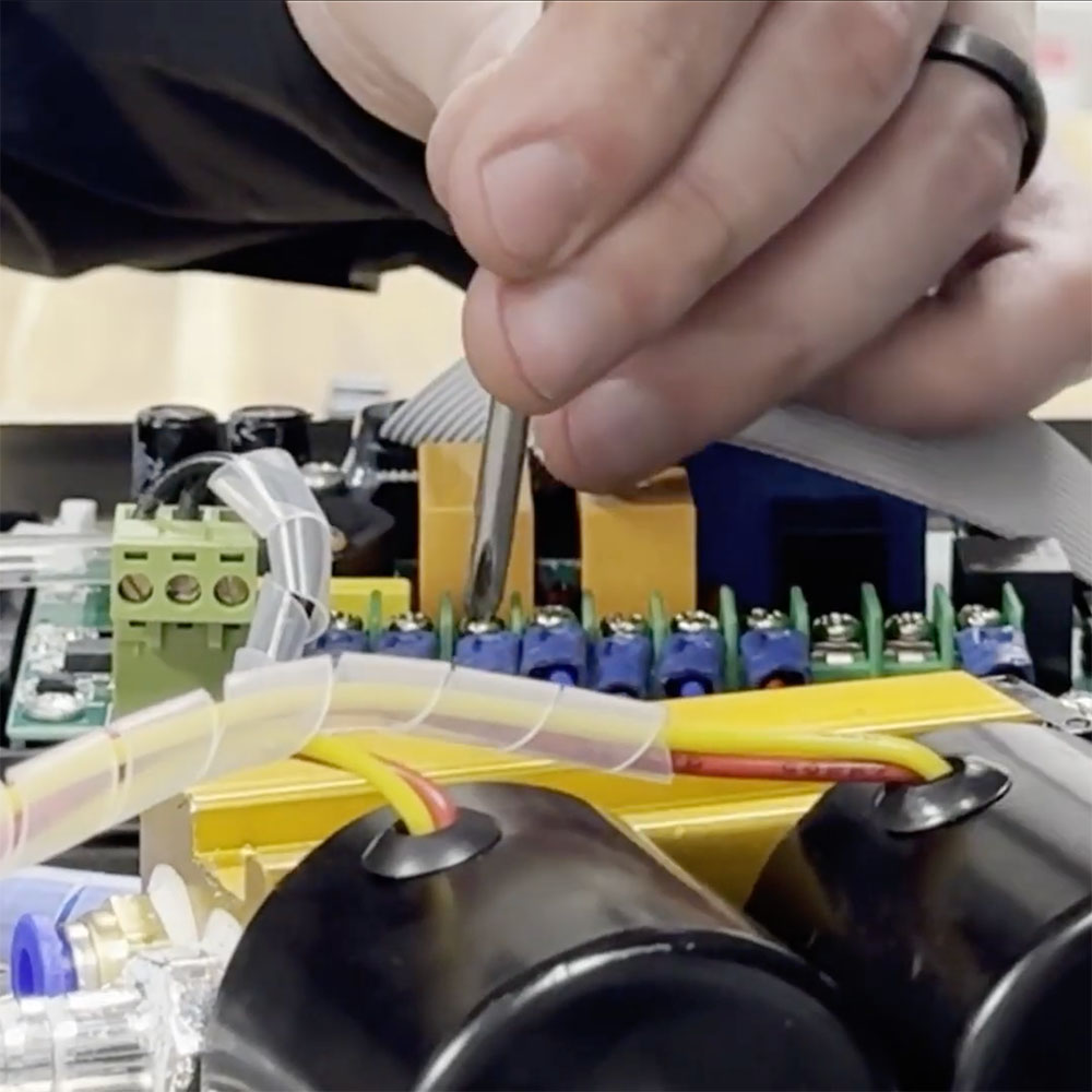
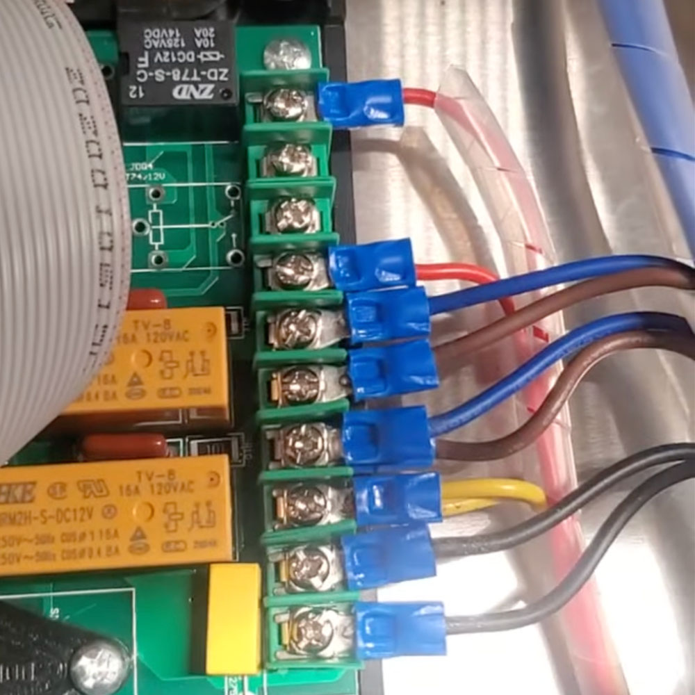
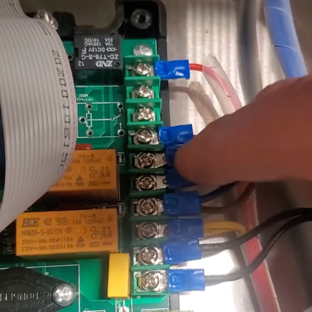
10. Unscrew the 3rd (securing the yellow wire) 7th, and 10th (red wires) screws and detach the wires.

CAUTION: Ensure the machine is centered on the 4×4 blocks before proceeding.

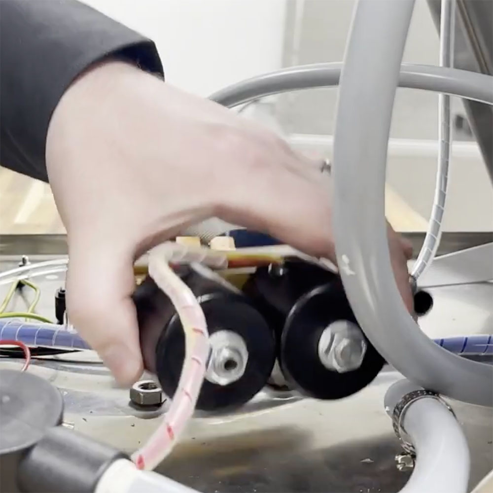
11. Use your right-angle #2 ratchet screwdriver to disconnect the valve assembly. The screws are on the bottom of the unit floor.

Replacing the Valve Assembly

12. Grab your new valve assembly!

NOTE: You will notice that your new valve assembly and hoses do not contain silicone. The silicone is simply a precautionary step during manufacturing. This will not affect accomplishing a full vacuum.

13. Use the 3mm Allen key to line up the hole of the valve assembly with the hole of the unit floor.

14. Tighten the screws using the right angle #2 ratchet screwdriver.

Reassembling

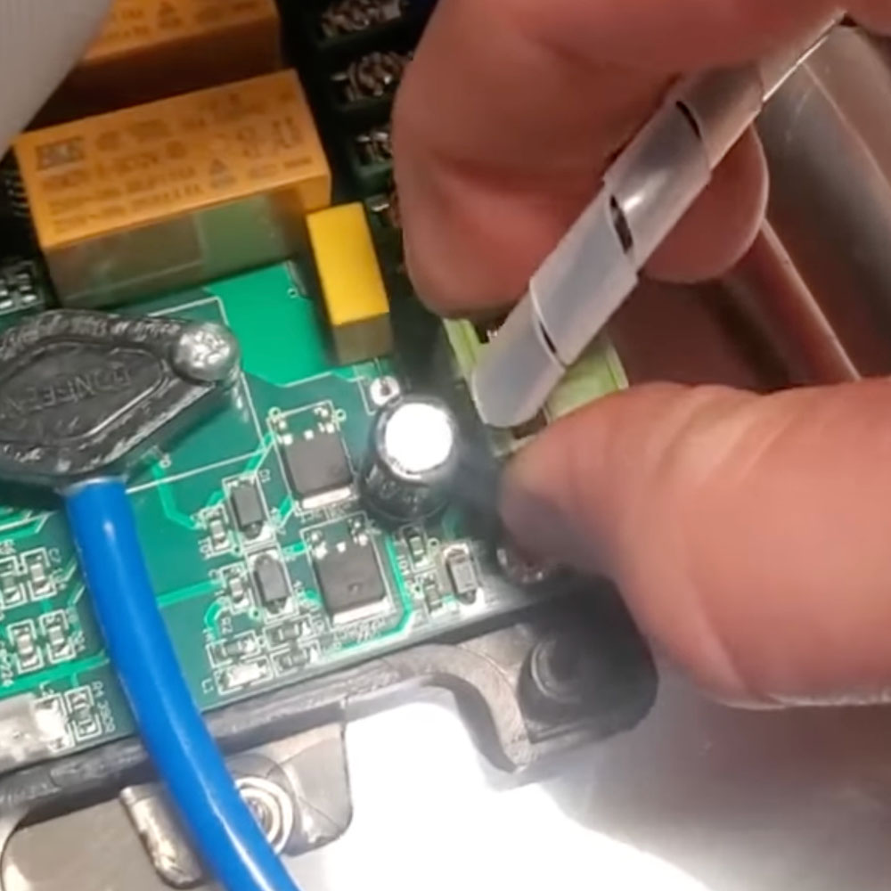
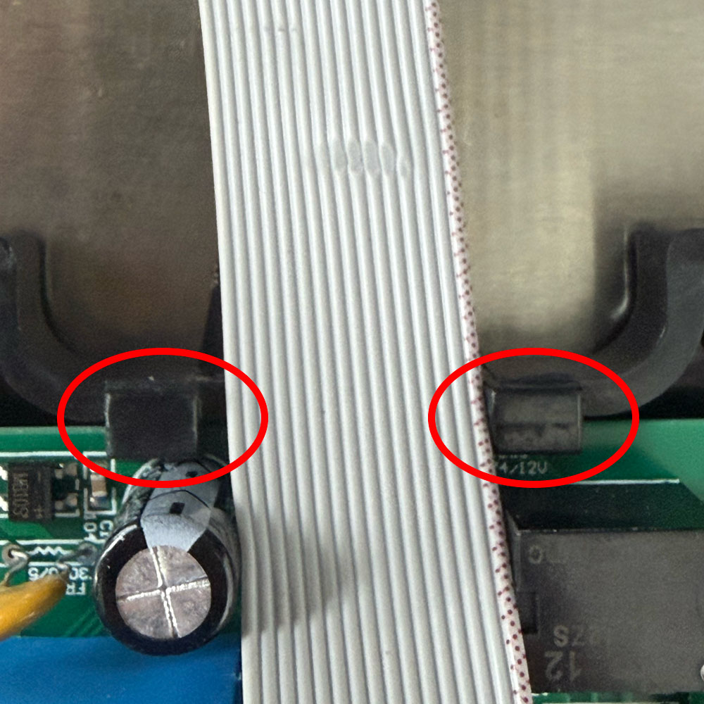
15. Fasten the yellow and red wire back with the 3rd, 7th, and 10th screws at the control board using the #2 Phillips screwdriver. USE IMAGE BELOW. Insert the clear hose that goes to the vacuum sensor.

16. Insert the clear hose that goes to the vacuum sensor.

17. Reinsert the hoses and the hose clamps using the flathead screwdriver.

18. Secure the black box over the control board using the #2 Phillips screwdriver.

19. Close the unit and secure the three Allen screws using the 3mm Allen screwdriver.

20. Run some test cycles!

Review the video below for a helpful visual on how to replace your vacuum valve assembly. Or give us a call to talk with our experienced and reliable service technicians. We also have our Live Chat app available for any questions, and, yes, you will be talking to real people!

Furthermore, check out our Vac100 parts categories to browse and learn more about additional replacement parts or accessories available. We look forward to hearing from you!

.
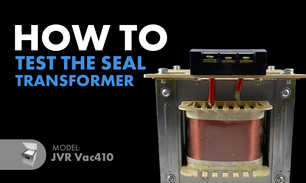
How to Test the Seal Transformer (410-61) Vac410 and Vac610

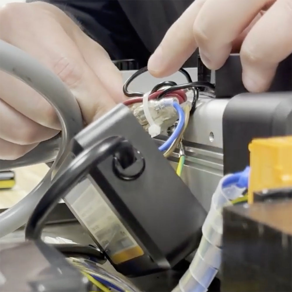
“You will likely save time and money if you take the steps to identify the diagnosis right from the start.”

Superior seal integrity is among the most important functions of a vacuum sealer. Without a sound vacuum seal, air seeps right back into the vacuum pouch, making the vacuum cycle completely useless. If you are experiencing seal failure, we’ve got you! Today, we will go over how to test a major component of the seal system in your Vac410 and Vac610 chamber sealers – the large seal transformer. This will aid in the process of diagnosing your unit when experiencing seal failure.

As an essential part of the power system, a transformer works to take the input power and turn it either into a higher or lower voltage to match the appropriate output before reaching its target. So instead of forcing unnecessary power through and killing the system, or missing enough power even to function, a transformer ensures the output power is just right to keep the system running smoothly. Transformers come in many different sizes, and each is manufactured to provide a customized function to fit the requirements of the system.

How does this apply to our Vac410 or Vac610 chamber vacuum sealer users? The seal transformer in your VacSeries unit steps the power down before heading to the seal bars in these units. This ensures the heat strips produce just enough heat for superior seal integrity without burning up. It feeds two seal bars and is wired in a series.

The Series:

Seal Transformer Input

Seal Transformer Output

First Wire

First Seal Bar

Second Wire

Second Seal Bar

Seal Transformer

This completes the series.

The seal system in a chamber vacuum sealer includes many components. Therefore, if you are experiencing seal failure, then it does not necessarily imply the problem lies with one singular part. You may benefit from checking for a burnt or broken seal heat wire first, as this is the most convenient part to inspect and the cheapest to replace. Overall, ensure you go through the processes to help rule parts in or out before purchasing one that might not be the problem. You will likely save time and money if you take the steps to identify the diagnosis right from the start.

Feel free to call our service technicians to help properly diagnose your unit.

#2 Phillips Screwdriver

Voltmeter

1. Remove the back panel using the #2 Phillips screwdriver.

Vac410 - Chamber Vacuum Sealer | Back Panel Open

2. Obtain the Voltmeter.

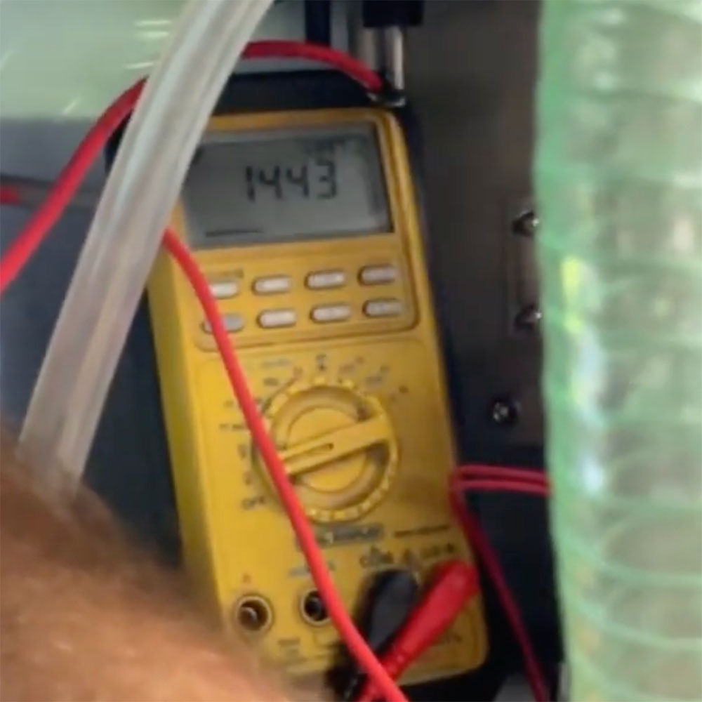
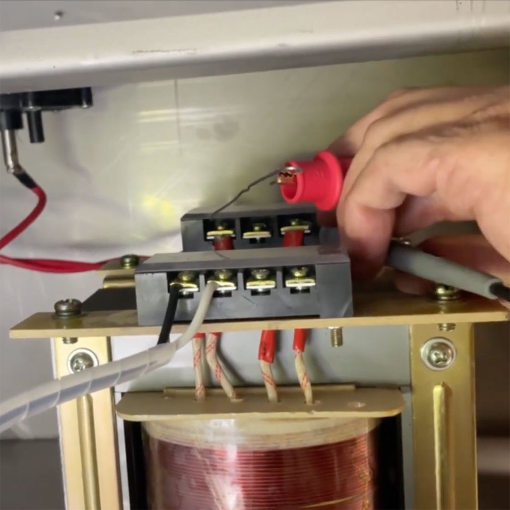
3. Feed 220 Volts into the input end (black and white wires). Your Voltmeter should read approximately 204V.

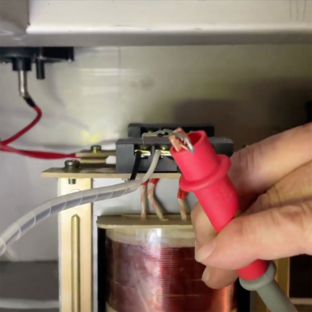
4. Now test the output side (directly behind the input end). The Voltmeter should read approximately 16V.

NOTE: If both input and output seem sound, it’s possible you could have a bad connection at one of the seal cylinders, or a heat wire could be broken on the seal bar.

Review the video below, created as a helpful in-action process to use as a visual reference. We always have service resources readily available on our website and YouTube channel.

Please feel free to give us a call if you need help diagnosing your machine. Our team here at JVR Industries is always ready to help. No automated systems here – when you call, you will talk directly to a human right from the start! Additionally, you can visit our VacSeries parts category and browse the replacement parts or other vacuum packaging products we have readily available. We look forward to hearing from you.

.
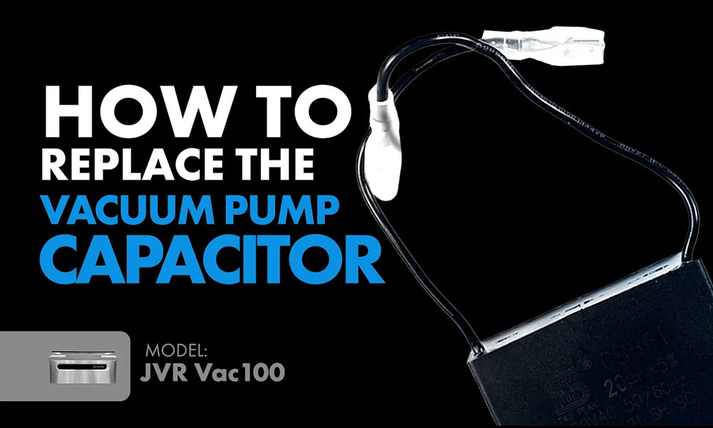
How to Replace the Vacuum Pump Capacitor (100-31) Vac100

“…replacing your vacuum pump capacitor may be the simple and inexpensive way to get your vacuum pump up and running again.”

The Vac100 chamber vacuum sealer is manufactured with many features to make your vacuum packaging process as convenient as possible. One of these features includes the vacuum pump capacitor. Vacuum pumps can fail to rotate internally in some very rare instances due to premature capacitor failure, and buying a replacement may be the simple and inexpensive way to get your vacuum pump up and running again. Doing this vacuum pump maintenance repair may save on other maintenance costs down the road.
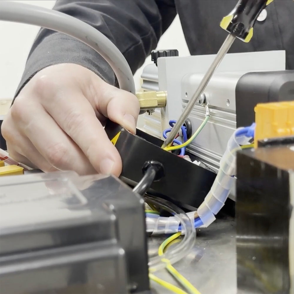
If you’re unsure whether your capacitor needs replacement, contact one of our service experts to help determine the cause of your vacuum pump malfunction.

3 mm Allen wrench

Pair of scissors

Number two Phillips screwdriver

Unplug the unit from any source of power.

Set the unit on a stationary counter with some extra space.

Clear the chamber of filler plates or other items that could fall when the body is hinged forward.

Remove Three Bottom Screws From Back Panel to Open the Machine.

1. Firstly, remove three Allen screws on the base of back panel. Lift the body forward and lock the hinge mechanism into place.

2. Secondly, use a number two Phillips screwdriver to remove four screws on black box of vacuum pump.

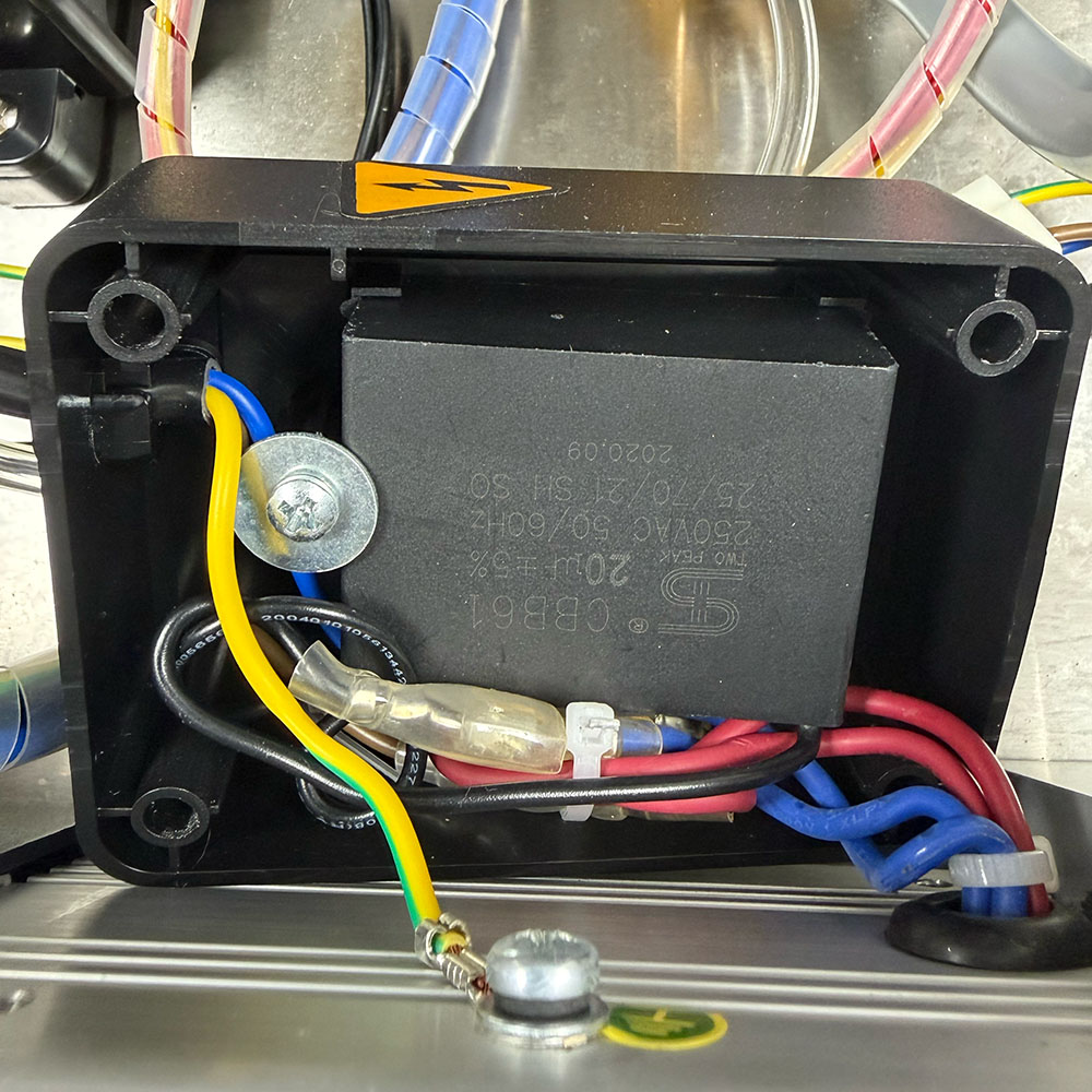
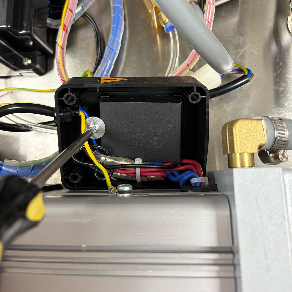
3. Then, once you’re inside the black box, you’ll see the capacitor. (NOTE: It’s the little black box inside the black compartment.)

4. There will be a number two screw and washer. Use a number two Phillips screwdriver to pop that off and set that to the side.

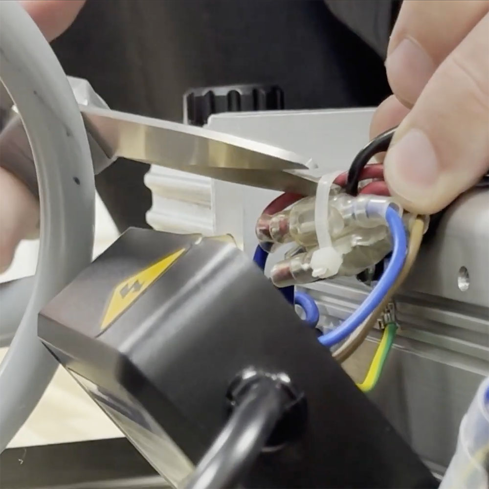
5. Remove capacitor. There will be two black wires running from the capacitor. Trace these two black wires into the bunch of wires. (NOTE: You may need to use scissors to cut the zip-tie holding the bunch of wires together. You may be able to work around this depending on how it was set-up, although cutting the zip-tie will make the replacement process easier.)

6. Grab your new replacement capacitor. Look for the text on one of the sides of new capacitor and set it next to the old capacitor so you can see where it will hook up.

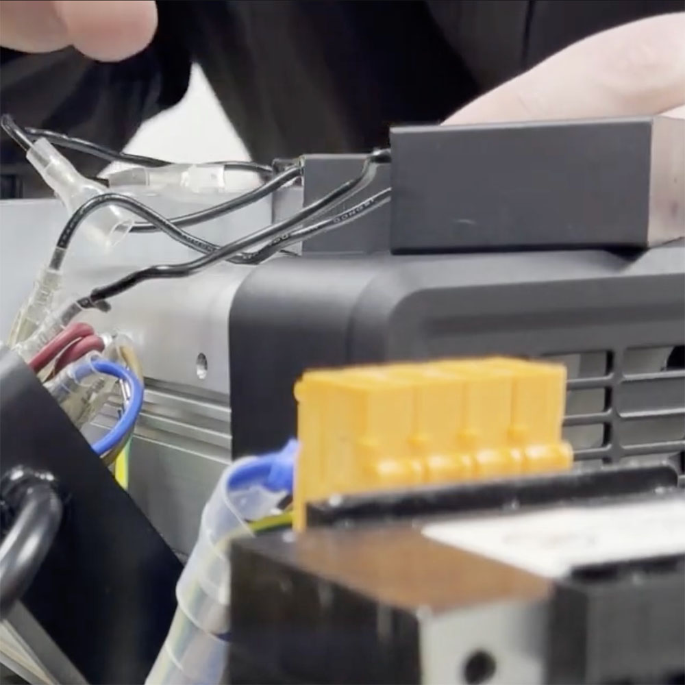
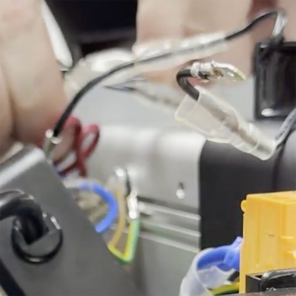
7. Untangle and pull apart the two black wires of the old capacitor, separating them from the bunch of wires. Pinch the female end (on the width of the wire), and pull the male end out.

8. Next, you will take the same side wire of the new capacitor and pop it on in it’s place.

9. Repeat last step for other side. (NOTE: If you had trouble getting the new wires back on after getting the old ones off, you may have opened up that channel a little bit too much. To solve this issue, you could just take pliers to crimp that back onto the male end of the wire.)

10. Once that is complete, grab the bunch of wires and zip-tie them back together.

11. Drop new replacement capacitor into the black compartment, screw it back on, and you’re ready to go

Have questions about the replacement process? We will be glad to help you out! Give us a call to talk directly to a service technician or email us at JVR@jvrinc.com.

.

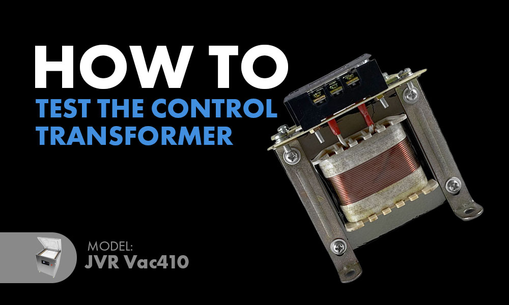
How to Test the Control Transformer (410-61) Vac410

“The control transformer ensures that consistent power is transmitted throughout the electrical delivery system with reliability.”

Did your unit cease transferring power, and are you unsure what part is causing the break in the circuit? Today, we will go through the simple steps of testing what part is the culprit, as well as the importance of a control transformer in the unit’s power system. When you think your machine is down, it is likely as simple as finding what part needs replacing or repairing. Let’s begin!

Function

The control transformer ensures that consistent power is transmitted throughout the electrical delivery system with reliability. Generally connected to the primary power source, the transformer accounts for regulating the primary power production. Initially, the primary power source produces more than enough power. Then the transformer works as a grounding system that has the ability to transform the current to only what the actual metal core circuit board needs. This is opposed to causing resistance or impedance, such as with a resistor.

They are often used in systems that require consistent power regulation for safety purposes, such as heating systems or other temperature and lighting control.

Design

During the manufacturing process, control transformers are purposefully made with materials to withstand the pressures it is expected to be under, considering their function. For example, epoxy resin is applied around the coils and acts as an effective insulator to protect from moisture. The development is to protect the circuits forming a straight line from the primary power source, leading to the rest of the circuit from overload.

Benefit

The transformer is an important component in manufacturing as it provides reliability, safety, and effective functionality of the power system.

If you are experiencing a power shortage, troubleshooting is necessary to find what connections are causing the problem. Although the control transformer could be the problem, it is rare when it experiences burnout. So the process will consist of what to test to identify which part of the electrical circuit is the problem. Instead of purchasing a part that may or may not be the problem, pull that voltmeter out of storage, and get to testing to locate that easy fix!

#2 Phillips Screwdriver

Volt Meter / Multimeter Devices

About the Method

This method will test the quality of any features that need replacing.

Use the volt meter to check for power at the following locations. If the voltage is measured lower than expected, this traces the trouble spot of the circuit.

Steps

Accessing the Vac410 Interior

Remove the back panel of the Vac410 using the #2 Phillips to expose the interior of the unit for testing.

Vac410 - Chamber Vacuum Sealer | Back Panel Open

Identifying The Problem

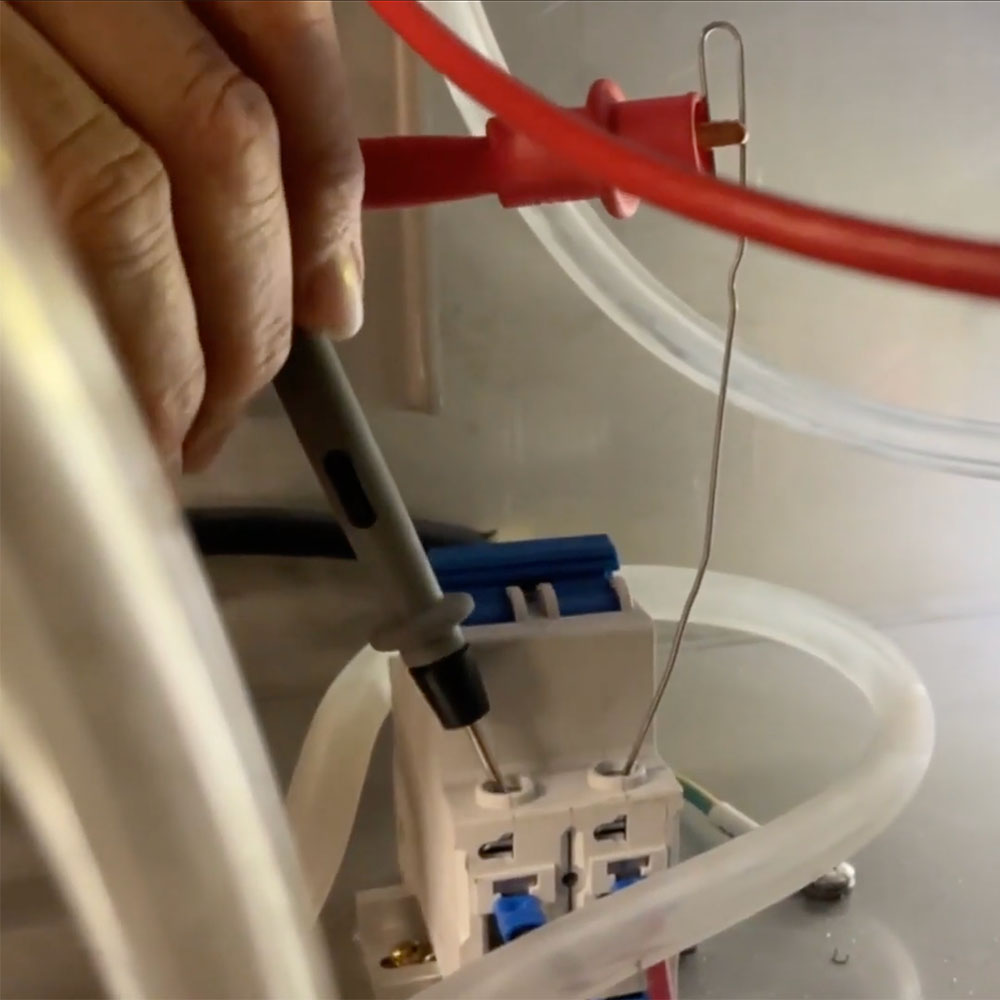
Use the point of the Volt Meter / Multimeter pin wires. Test the following and use the video below for guidance if needed:

Main Breaker (+/- 210 V)

Voltage going into the transformer from the main breaker; located towards the front of the transformer (+/- 210 V)

Voltage leaving the control transformer; located at the two farthest points on the transformer (+/- 27 V)

Lastly, check the connection at the PC board (PCB) (+/- 27 V)

Once you are finished troubleshooting, you should now know which part of the circuit requires repairing or replacing.

Here at JVR Industries, we look to support our customers in any way we can. If you have any questions about the troubleshooting process, which part to purchase, the repair process, or other service help on your chamber vacuum machine, please give us a call and ask for our service department. We are always ready to help!

.

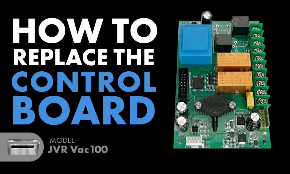
How to Replace the Control Board (100-51B)

How To Replace Control Board (100-51B): JVR Vac100 Chamber Vacuum Sealer


“Our service technicians are always ready to provide help with 50 years of vacuum packaging experience

The Vac100 chamber vacuum sealers are equipped with a feature that allows you to program them with individual vacuum-sealing times for liquids and foods. To keep producing the same results, proper upkeep is required. Keep in mind that an incorrect diagnosis of the power circuit can increase the likelihood of further issues and a larger price to pay. Protect your chamber sealer by getting the correct form of diagnosis.

Once you have received a proper diagnosis of a faulty control board (100-51B), then you can proceed with the replacement process below.

Allen Key

#2 Phillips Screwdriver

*Place the unit on a sturdy table with ample space.

*Ensure the Vac100 is powered off and unplug the unit from any power source.

*Make sure the chamber is empty of filler plates, bags, or any other loose items.

Prep - Remove Screws From the Back

1. Use the Allen key to unscrew the three Allen screws along the base of the back panel.

2. Hinge the external body forward and lock the hinge mechanism in place.

3. Use the #2 Phillips to remove the black plastic enclosure in order to expose the control board.

Removing the Old Control Board

4. Remove the blue hose (somes machines have a clear hose) by lightly wiggling it back and forth.

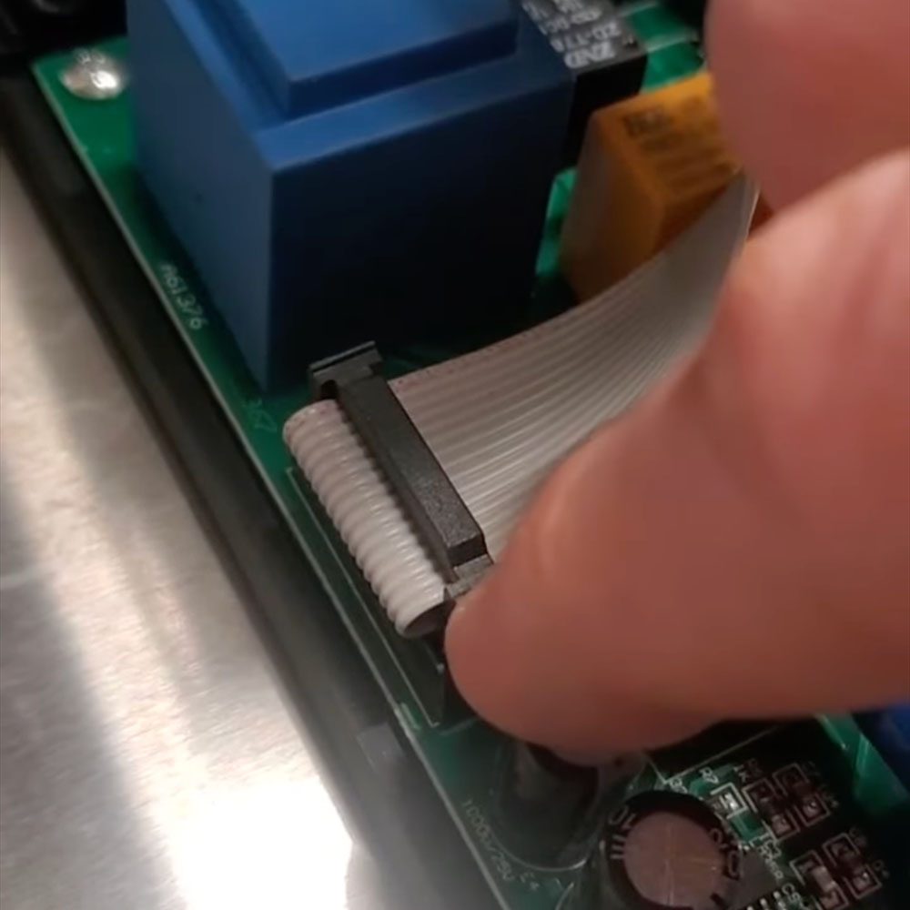
5. LIGHTLY pry off the grey ribbon – it is fragile.

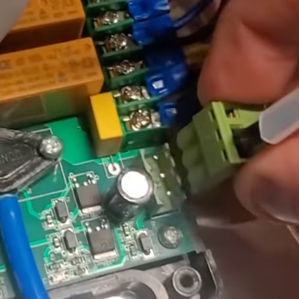
6. Detach the green connector.

7. Use a #2 Phillips to loosen the screws to each input wire and remove each.

TAKE NOTE of where each was placed so you can place them back in their respective areas.

8. Finally, remove the old control board with the #2 Phillips.

Installing the New Control Board

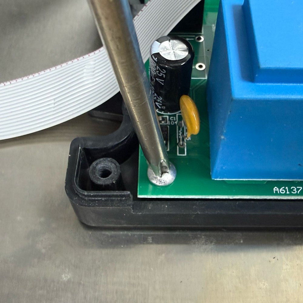
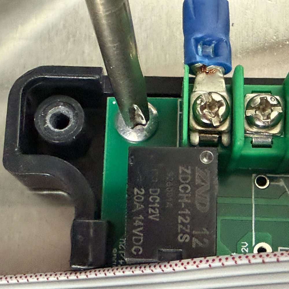
9. Replace with the new control board and secure the 4 screws.

10. Secure the input wires in their respective places, then tighten the screws.

11. Reinsert the blue/clear hose and grey ribbon, then click the green connector into place.

12. Secure the black cover over the control board.

NOTE: When reinstalling the black cover, make sure the grey ribbon runs behind the blue tab on the control board and fits in line with the groove on the black cover. If not in the correct area, the grey ribbon will pinch between the enclosure and the floor, and the box won’t be able to secure properly.

Review the video link below for a helpful visual interpretation of the process. For further information or help diagnosing your unit, give us a call during our business hours or email anytime, and we will get back to you promptly. Our service technicians are always ready to provide help with 50 years of vacuum packaging experience stacked behind us. We are here in hopes of helping your chamber vacuum sealer last for life and keep it out of the landfill, setting us apart from our competitors.

.

How to Replace/Install the Inline Vacuum Filter (100-92-ASSY)

How To Replace/Install The Inline Vacuum Filter (100-92-ASSY): JVR Vac100 & JVR Vac110


“Adds that extra protection to your vacuum pump

Now offering a new part to optimize the protection of the rotary vane oil vacuum pump – the heart of your vacuum sealer that determines the longevity of your JVR Vac100 and Vac110 chamber sealers. Let’s look at how the inline vacuum filter might apply to your vacuum packaging endeavors and how to install/replace it.

A new part has been released for those who vacuum package flour or similar dry, powdery products. Known as the inline vacuum filter, this part adds extra protection to your vacuum system to ensure the powder does not enter the vacuum hose and eventually the vacuum pump. Although chamber vacuum sealers are manufactured with an internal vacuum system to vacuum seal liquids and powdery items, spill overs are always possible. This means the vacuum pump requires parts helpful in ensuring its protection to maintain longevity.

Just like the oil pump protects from moisture when vacuum packaging liquids, the inline filter will add extra protection against any powdery particles that may enter the vacuum system. The part comes as an assembly including the housing and filter.

Vac100 Inline Vacuum Filter

As the filter becomes polluted, you will need to replace it to maintain optimal functioning. If you use your unit routinely, we would recommend inspecting the filter once a month for pollution. Instead of purchasing a whole new part, we offer a pack of 3 replacement filters (100-92F) to install in the inline vacuum filter housing. This makes for easy replacement down the line, and you have extra for later!

3 mm Allen Key

Strap Cutters / Scissors

Inline Vacuum Filter (100-92-ASSY)

Make sure no filler plates or other items are in the chamber before you begin.

Use a stable surface to work on. If you keep your unit on a cart, it is better to transfer it to a stationary countertop.

Power off and unplug your JVR Vac100 / Vac110.

1. Turn the unit so that the back panel is facing you. This should not scratch the surface area if you are using the Velcro feet supplied to you.

2. Use the 3 mm Allen key to unscrew the bottom three Allen screws securing the external body to the base of the unit.

3. Lift the body forward and lock the hinge mechanism into place.

4. Use strap cutters or basic scissors to cut the vacuum hose that forms a connection between the valve assembly and the inlet check valve located on the vacuum pump in half.

5. Install the inline vacuum filter by inserting each filter fitting into either section of the hose.

NOTE: THE ARROW ON THE INLINE FILTER SHOULD POINT TOWARDS THE VACUUM PUMP.

6. Cut any excess hose off where it attaches to the filter so that the filter does not block the external body from closing.

NOTE: Always cut less than what you think, as not to accidentally cut too much hose off and have to replace that too!

In search of further information? Play the video below to review a visual representation of these steps. Or, contact our service technicians here at JVR Industries. With 50-plus years of information and experience behind them, our company stands out from our competitors by offering the service and parts for the duration of your machine’s lifespan.

Browse additional parts and accessories for both the JVR Vac100 and Vac110 chamber sealer categories.

.

How to Change the Vacuum Pump Exhaust Filter (RVS20-32, 310-33)

How to Change the Vacuum Pump Exhaust Filter (310-33, RVS20-32): Vac310


“The exhaust filter function encourages the recycling of clean oil and efficient vacuum pump performance.”

Our promise stands true that we will consistently be providing top-notch service for your machine to keep it up and running for as long as it takes! Today, we will go over the role and importance of replacing your Vac310 exhaust filter and how to replace it to maintain optimal vacuum pump performance.

Exhaust Filter (White Pump, 310-33 or RVS20-32): Compatible with SECOND generation Vac310 (1-Bar) and Vac310 (2-Bar) chamber vacuum sealers that house the WHITE pump. Continue to the next section.

NOTE: If you own a FIRST generation Vac310 (1-Bar) or Vac310 (2-Bar) chamber vacuum sealer housing a GRAY vacuum pump, then read here for instructions on how to replace the compatible exhaust filter (310-32).

Vac310 Vacuum Pump Exhaust Filter (White Pump)

The main purpose of the exhaust filter is to provide a reliable form of protection for the vacuum pump system against any excess moisture from liquid products or dust that the vacuum could carry in from the chamber. During operation, the oil is suspended in the air creating an oil mist that is caught and recycled while, simultaneously, any particles are filtered out so that your pump expels clean air. The exhaust filter function encourages the recycling of clean oil and efficient vacuum pump performance.

For an oil pump that can handle pulling 99% of air from the chamber bag, regular upkeep is a must. With proper upkeep, your Vac310 will run proficiently for years to come – well over 10 years is normal! Thankfully, service is made easy on your machines, so you can fit a simple part replacement into almost any busy day.

Exhaust Filter Benefits

Boosts the energy efficiency.

Decreases energy consumption.

Ensures your rotary vane oil-lubricated pump expels clean air.

A number of circumstances can indicate the need to change your exhaust filter.

General Upkeep: We recommend replacing the exhaust filter once a year.

Smoke: You notice a puff of smoke at the beginning of a vacuum seal cycle.

Odor: You notice smoke or oil odor coming from the exhaust exiting the JVR Vac310 vacuum pump.

Difficulty Level

Moderate

Time Required

Approximately 30 Minutes

Tools Needed

#2 Phillips Screwdriver

13 mm Combination Wrenches

5 mm Allen Wrench (comes with the Vac310)

2″x4″ Wood Block (x2)

Vac310 Exhaust Filter (White Pump, 310-33 or RVS20-32)

Power off the unit and unplug it from its power source.

Place your vac310 chamber vacuum sealer on a stable surface.

Latch the lid closed.

Accessing the Vacuum Pump

1. Use #2 Phillips to unscrew all six screws securing the back panel. Make sure to hold the base of the panel at the last two top screws to keep it from falling.

2. Place 2×4 wood blocks under each back leg to prop up the unit.

3. Use the 13 mm Combination Wrench to remove the four nuts found underneath the unit that secures the pump. We recommend using the ratcheting end, but either works!

4. Turn the vacuum pump about 45° to access the side closest to the side of the unit.

Changing the Vacuum Pump Exhaust Filter

5. Remove the filter cap using the 5 mm Allen Wrench.

6. Remove the exhaust filter.

7. Set the circular disc and spring aside to reuse.

8. Acquire your new exhaust filter – make sure not to lose the new O-ring!

9. On the opposing end, remove the rubber sleeve.

10. Reinsert the spring and circular disc in this order.

11. Grab the exhaust filter by the end of the thread and insert it directly, base first, into the pump until you tap the opposing side.

12. Use the circular disc as a reference to ensure the exhaust filter is centered.

13. Secure the filter cap over the filter and secure the screws using the Allen wrench.

Last Steps

14. Rotate the vacuum pump back to its original position.

15. Secure the nuts at the bottom of the unit using the 13 mm Combination wrench.

16. Reapply the back the back panel.

17. Remove the 2×4 blocks.

Your unit is all set for optimal functioning!

Have further questions? You are promised lifetime technical support for your VacSeries machine offered by our highly experienced and personable technicians! Please do not hesitate to reach out via phone or email.

.

How to Replace the Seal Bar Lift Pistons (100-25) JVR Vac100

How To Replace Seal Bar Lift Pistons (100-25): JVR Vac100 – Chamber Vacuum Sealer


“Self-maintenance is pretty easy when it comes to the JVR Vac100!”

If the vacuum bags are not sealing effectively, the unit will fail to keep food fresh. Additionally, this will limit other endeavors such as sous vide, marination, and the use of retort seal bar accessories. Seal failure could imply a leak in the seal bar piston, impairing the ability of the positive and negative air flow to operate in tandem for even force along the seal bar. Let’s get started with the replacement of the seal bar piston (AKA seal diaphragm assembly).

NOTE: Vacuum leaks can result from various factors, including the seal bar (100-15), lid chamber gasket (100-10A), lift piston (100-25), and hose loosening. Please contact us if you require assistance with diagnosing the issue.

Allen Key

Nut Driver / Small Pliers

#2 Phillips (stubby works best)

CAUTION: The unit will remain plugged in during the testing process. Everything, electrically, is well insulated. Regardless, remain cautious.

Ensure the Vac100 is on a stable counter.

NOTE: Before beginning the process, take note of the lowest vacuum you can achieve with everything attached (e.g., 0.298 MPa).

Accessing the Seal Diaphragm Assemblies

  • Orient the Vac100 so you can access the back.

  • Use the Allen key to remove the bottom three Allen screws from the back panel.
  • Ensure the chamber is empty of filler plates, etc., then tilt the external body forward.

  • Notice the hose that goes from the valve assembly, then splits to each of the seal diaphragm assemblies (two gray, plastic components).

Run a Test Cycle

  • Remove one of the hoses.
    • CAUTION: Do this with control, as your hand might spring back, causing an injury.
  • Set the vacuum cycle time to the same as you normally would when packaging.
  • Close the chamber lid to begin the vacuum cycle, then block the end of the hose with your finger.
  • Check the vacuum level on the control overlay. If the vacuum improves when you block the hose, then you have identified the seal bar piston with the leak.
  • Reset the hose you just tested.
  • REPEAT this process with the other hose.
  • Once you have identified the faulty lift piston, it’s time to replace it.

Removing the Old Seal Bar Piston

  • Disconnect the unit from its power supply and move the cable out of the way.
  • Position the unit so you can easily access the seal bar lift pistons from the interior.
  • Disconnect the gray hose from the piston.
  • Remove the seal bar from inside the chamber.
  • Use the nut driver/pliers to disconnect the 7mm electrical connection (keep the screw).
  • Use the #2 Phillips screwdriver (stubby) to remove the screws securing the list piston.

  • Wiggle the old seal bar lift piston out. DON’T LOSE THE SPRING.

Installing the New Seal Bar Piston

  • Wipe the shaft of the new seal bar piston and apply a small amount of vegetable or mineral oil to prevent seal damage.
  • Slightly push in the short end of the piston while inserting it into the housing. This creates a buffer zone.
    • NOTE: This avoids the diaphragm forcing itself down and jamming during the process. The seal diaphragm will not fully seat in the housing, causing leaks during the vacuum-seal cycle.
  • Wiggle the seal bar piston into the housing, being careful to keep pressure on the shaft.

  • Secure with the four screws.
  • Reattach the gray hose.
  • Hand-thread the terminal, then secure with the 7mm nut driver, enough so it won’t spin off.

Test Again

  1. We would suggest reconnecting the unit to its power source and re-testing the Vac100.
  2. If you are still getting a leak during the vacuum cycle, it is likely the diaphragm was not seated properly in the housing during installation.
  3. Once you have confirmed that the new seal diaphragm works, you can close up and secure the external body with the Allen screws.

Self-maintenance is pretty easy when it comes to the JVR Vac100! However, feel free to call or watch the video below for further assistance. If you have further questions about the replacement process, please feel free to give us a call. Our service technicians have ample experience servicing vacuum packaging machines, some with over 30 years!

For additional VacSeries replacement service videos, check out our JVR Industries YouTube channel. We also provide a variety of additional means of contact options include email, LiveChat, and phone!

.

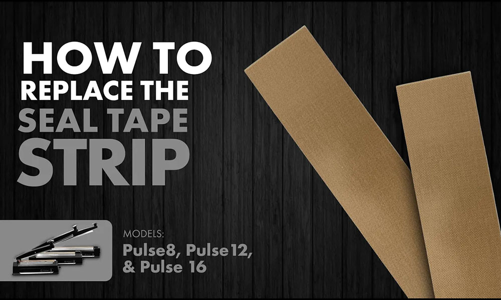
Hot to Replace the Seal Cushion Strip, PulseSeries

How To Replace Seal Cushion Strip (P08-04, P12-04, P16-04)


“Many replacement parts are kept in stock…”

Looking to replace the seal cushion strip on your pulse sealer machine? Continue reading below to follow along with these quick and easy steps on seal cushion strip replacement for efficient bag sealing!

Not sure when to replace your seal cushion strip? Our team here at JVR Industries has pride in carrying more than 50 years of experience, and one of our service technicians would be more than happy to help you. You can contact us by email at jvr@jvrinc.com or by phone at 716-206-2500.

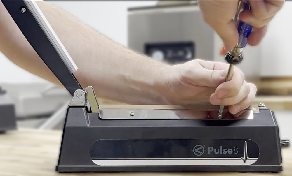
No tools are needed for this replacement process: everything can be done simply by hand. (Note: Handle the seal cushion strip carefully during installation.)

Estimated to be about a 1-2 minute process.

Make sure your pulse sealer is on a clean and stable flat surface (table, countertop, etc.) to protect the machine during maintenance.

Power off your unit and disconnect from the power supply.

Disassembly

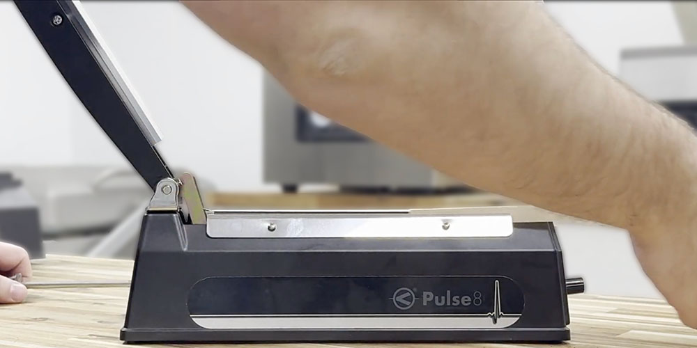
  1. Open the arm of your heat sealer.

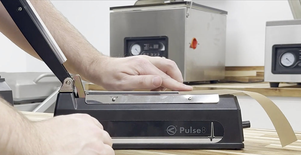
2. Once the arm is lifted, you will have a clear view of the old seal cushion strip. Remove the old seal cushion strip by sliding it up and off the machine arm.

Replacing the Seal Cushion Strip

3. Grab the new replacement seal cushion strip, and reinsert the strip the same way you removed the old one, except this time you will slide the new replacement strip down onto the arm of the heat sealer machine.

4. Close the arm of the heat sealer machine.

Now, your machine has a brand new seal cushion strip which will ensure top quality pulse sealing when using your PulseSeries machine.

Check out our YouTube channel for additional content on how to replace wear and tear parts on your Pulse sealer. Or give us a call to talk with our experienced and reliable service technicians. We also have the option to utilize our Live Chat app for any questions. Find security in knowing you will be talking to real people!

Furthermore, search our website and check out our PulseSeries parts categories to browse and learn more about additional replacement parts or available accessories! Many replacement parts are kept in stock, allowing us to ship items quickly. Each product page clearly displays the price of each item and compatible machine types so you can choose what replacement part you need with confidence.

.

How to Change the Exhaust Filter 100-32 Thumb

How to Change Pump Exhaust Filter (100-32): JVR Vac100


Filtering is a medium that combines powerful performance and superior separation levels.

Part of what makes the JVR Vac100 the best chamber vacuum sealer is its oil vacuum pump. The pump is the heart of all JVR Industries VacSeries chamber vacuum sealers and, if maintained regularly, will provide you with years of unmatched advantages. These include increasing shelf life, preventing freezer burn, sealing mylar bags, and a way of optimally marinating your steak before sous vide cooking. To keep the vacuum sealing process running smoothly with an optimal vacuum, regular replacement of the vacuum pump exhaust filter must take place.

Even though you keep your chamber clean (right?), there are always situations wher dust will get sucked into the system when the vacuum is applied. Or maybe you are vacuum sealing liquids and it reaches the cold boiling point due to the intense vacuum and it’s not caught on time so some contents might get sucked in. These are both scenarios that make the filter necessary for the functioning of the vacuum pump.

What Does the Vacuum Exhaust Filter Do?

Prevents dust and particulate matter from entering or exiting your system and contaminating the vacuum pump filter elements.

Boosts the energy efficiency of your unit.

Decreases energy consumption.

Ensures your rotary vane oil-lubricated pump expels clean air.

How Does it Work?

During typical operation, oil vacuum pumps produce a small oil mist that stays suspended in the atmosphere. The oil mist production is filtered during operation which catches and removes it before the air is expelled through the exhaust. Filtering is a medium that combines powerful performance and superior separation levels.

Additionally, layers of premium filtration material secure the oil mist when it comes through the oil filter encouraging recycling. The ability to recycle expensive lubricating oils is now made easy as oil particles rejoin and are reused by the vacuum pump. You save money on oil!

If you do not notice any indications, we recommend replacing the exhaust filter once a year for upkeep.

Indications that the filter element needs replacing in your chamber vacuum sealer:

Smoke: You notice a puff of smoke at the beginning of a vacuum seal cycle.

Odor: You notice smoke or oil odor coming from the exhaust exiting the JVR Vac100 vacuum pump.

NOTE: Feel free to utilize the skip function by pressing the down arrow if you notice these issues during a vacuum sealing cycle.

Difficulty Level: Easy

Time Required: 5-10 Minutes

Tools Needed: #2 Phillips Screwdriver & Allen Key (3mm)

Replacement Filter: 100-32, OR comes with the 100-MP Maintenance Pack along with other necessary parts for maintenance. 

Please complete all these steps before beginning the replacement process to ensure the safety of yourself and the chamber vacuum sealer.

1. Remove all contents from inside the chamber of your Vac100 including filler plates as the body will be tilted upright.

2. Make sure to power off the chamber vacuum sealer and unplug the IEC power cable.

3. Ensure your unit is resting on a stable surface.

Accessing the Internals of the JVR Vac100

To access the vacuum pump exhaust filter, you first need to access the internals of the machine.

1. Use the Allen key (3mm) to remove the three Allen screws found on the back panel of the unit.

2. Once the screws are removed, slowly and carefully hinge the body of the machine forward.

3. Press a finger against the hinging mechanism located on your right side from the back view to lock the hinged body in place.

Accessing the Exhaust Filter

4. Use the Allen key (3 mm) to remove the black exhaust cover by unscrewing the four screws securing it. You can locate this cover on the vacuum pump right above the sight glass.

5. Once you have a view of the exhaust filter, use a #2 Phillips screwdriver to loosen the Phillips screw located at the center of the filter holding it in place.

6. Remove and KEEP the screw and washer from the filter. Discard the old filter.

7. You can either use the old O-ring found on the base of the removed exhaust filter or simply use the new one that comes with the new replacement filter!

8. Place the O-ring on the new filter.

9. Insert the new filter in the pump and secure it with the pre-existing screw and washer using the #2 Phillips screwdriver.

The Final Steps

10. Secure the four screws holding the black exhaust cover with the Allen key (3mm).

11. Close the body of the chamber by loosening the hinging mechanism.

12. Reinstall the three screws at the back of the machine using the Allen key (3mm).

You’re all set!

Register your Vac100 to receive reminders on standard oil changes, pump exhaust filter changes, and more! Receive updates on your unit as well as general support. Register your Vac100 HERE.

Would you like to see a visual for the replacement process? Watch this video that takes you through the step-by-step procedure of replacing your Vac100 exhaust filter.

If you have any further questions about the replacement of the exhaust filter or about additional upkeep of your chamber vacuum sealer, do not hesitate to reach out! Our service team is always eager to help with years of experience! Give us a call during our business hours or email anytime.

.

JVR Industries, Inc. 100 W. Drullard Ave., Lancaster, NY 14086  –  Get DirectionsPhoneStore Hours

Explore Our Commitments To Our Customers

If you have any questions, please call us at (716)206-2500

© JVR Industries Inc. – Specializing in Vacuum Packaging, Since 1972 | Powered By Graphic Lux